Thread & bore
Metric or inch threads to your specification; blind or through features; plain bores and fit-related requirements.
MADE TO PRINT
Bring us the geometry, interfaces and requirements. We support custom insert projects from early information through manufacturing and delivery coordination.
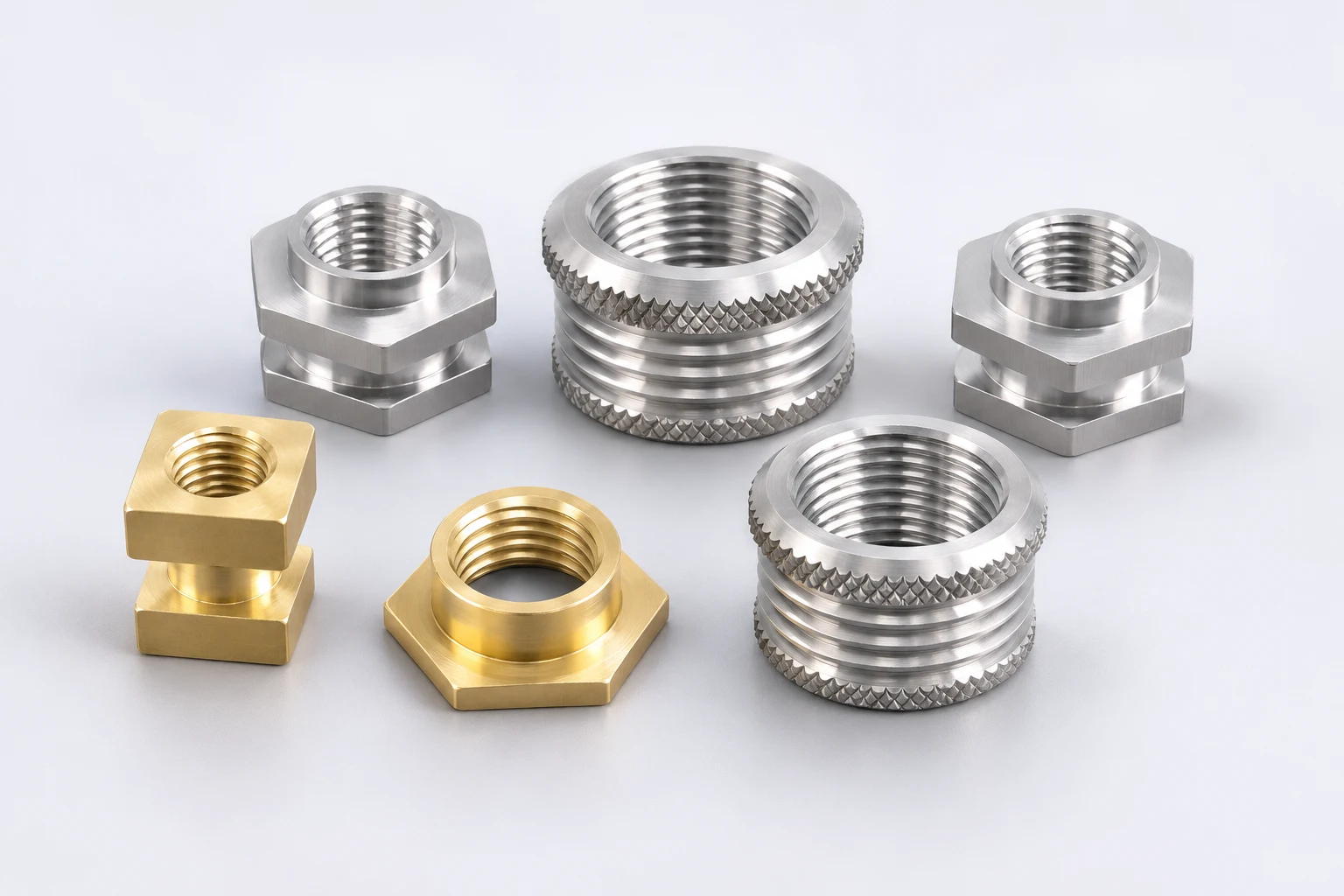
CUSTOM GEOMETRY
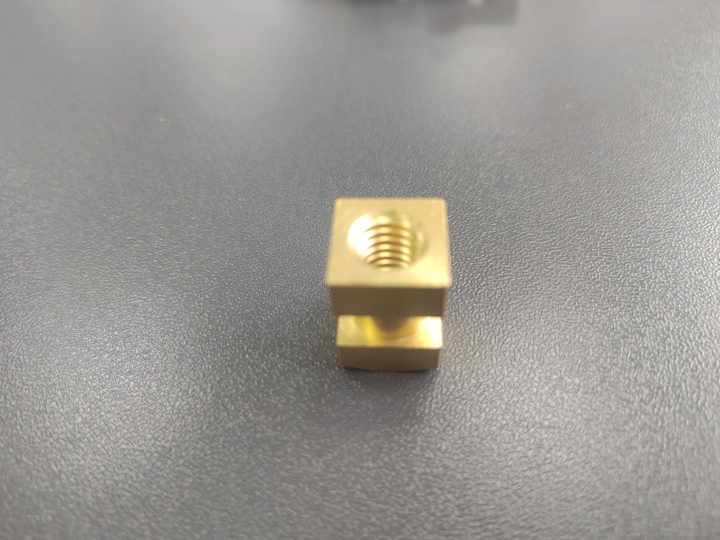
Two locating faces and a reduced central section.
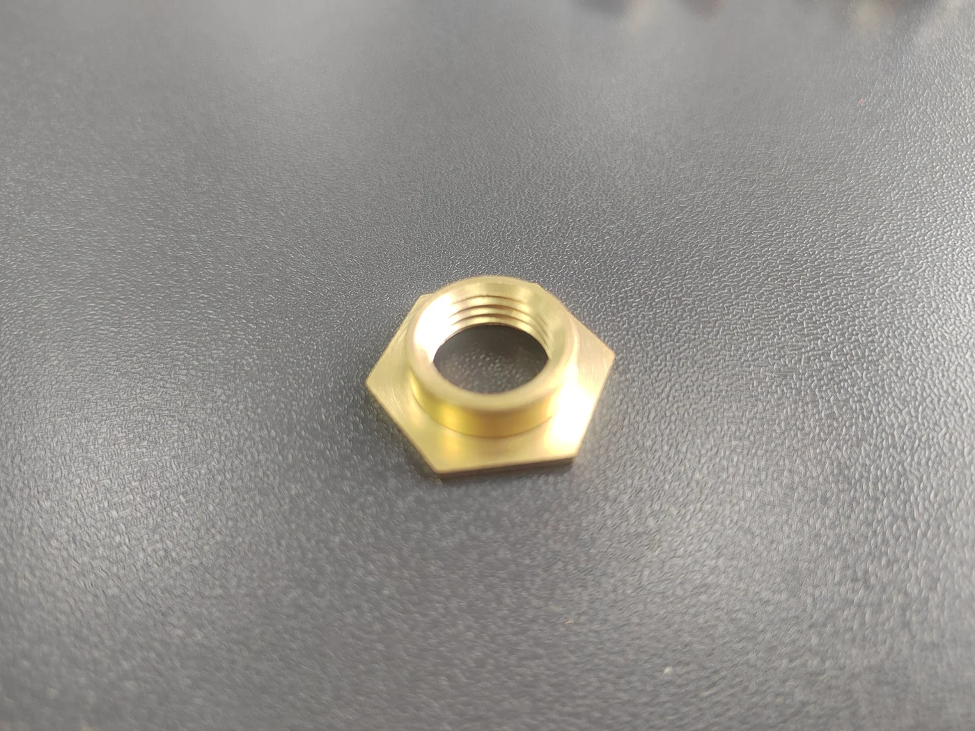
An internal thread combined with a seating feature.
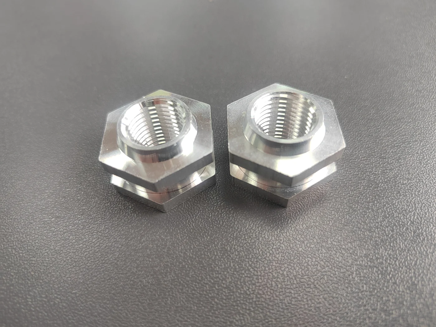
Separate profile and shoulder features in one part.
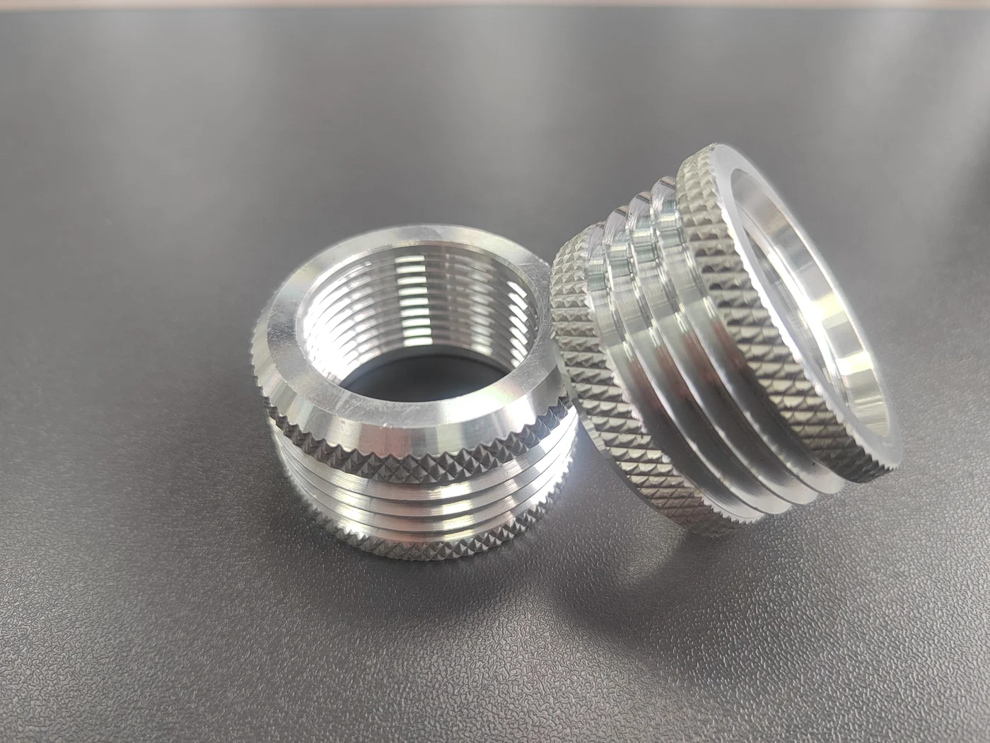
Circumferential grooves and knurled retention features.
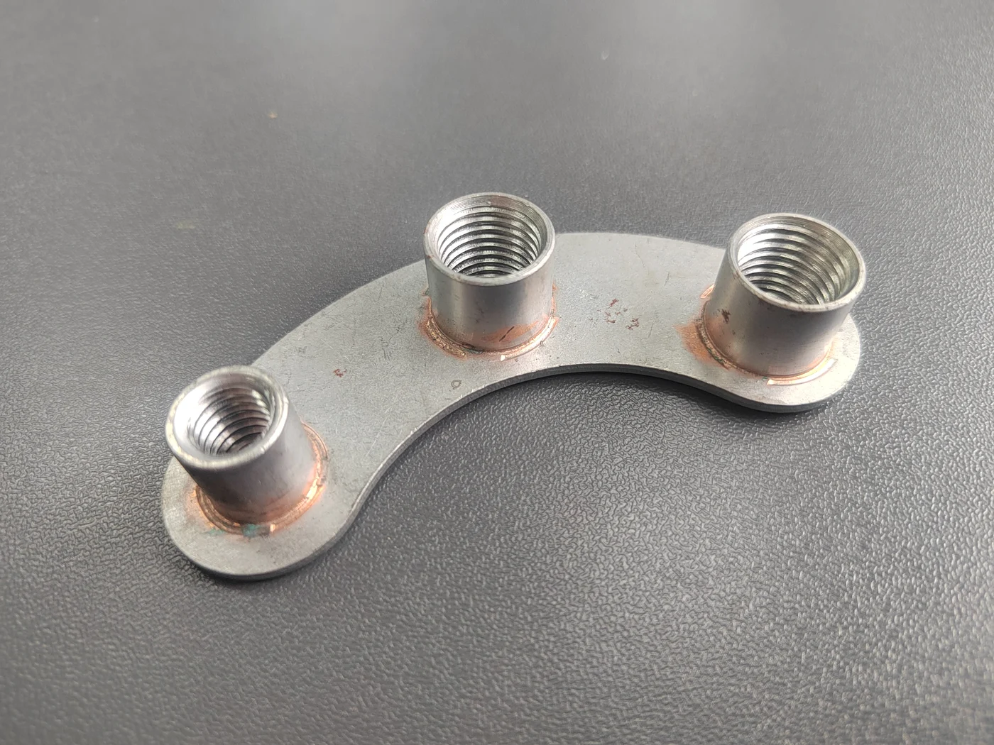
A connected geometry with more than one interface.
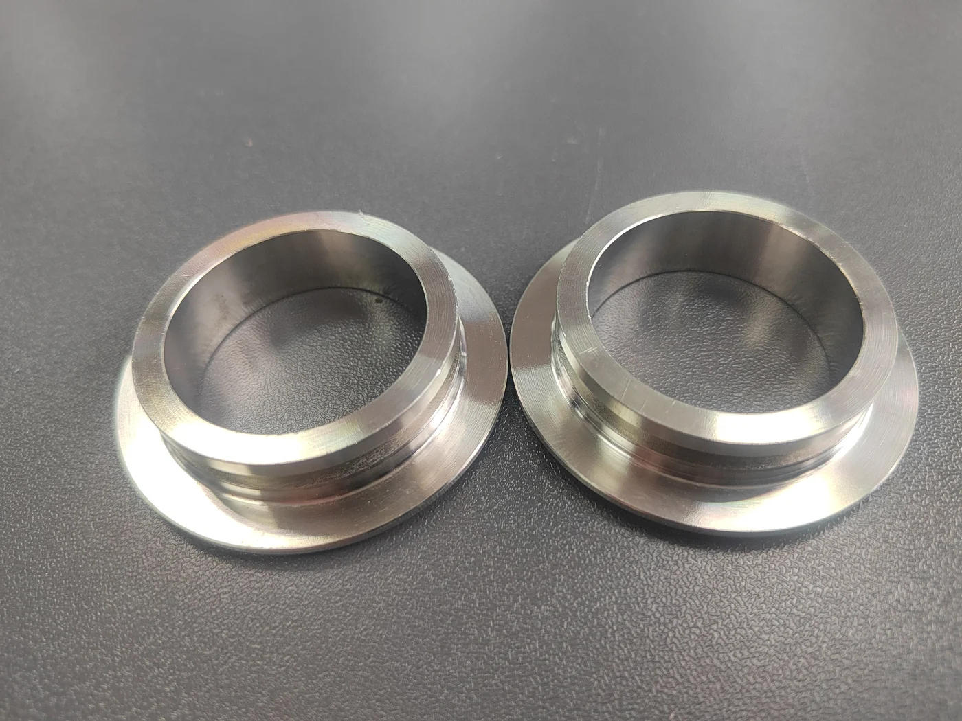
A plain bore with external locating features.
Original Crossland project photos. Geometry examples are not stock listings; material, size and installation suitability are defined for each project.
DESIGN INPUTS
Metric or inch threads to your specification; blind or through features; plain bores and fit-related requirements.
Knurls, grooves, shoulders, flats, flanges and other drawing-defined external features.
Threads, studs, locating surfaces, sleeves and multiple attachment points in one geometry.
Specified material grade, finish, corrosion exposure, appearance and document requirements.
PROJECT WORKFLOW
| Stage | What we establish |
|---|---|
| Initial review | Available drawings, sample information, application and requested quantity. |
| Technical clarification | Critical dimensions, tolerances, host geometry, installation and material. |
| Quote and sample plan | Scope, sample quantity, tooling if applicable, timing and acceptance basis. |
| Production approval | Agreed drawing revision and any required sample or inspection approval. |
| Repeat supply | Consistent part identification, revision, packing and documentation requirements. |
NO DRAWING YET?
Send clear photographs from the top, side and underside, one scale reference, the mating component and the dimensions you know. Tell us what the part must do and what needs to change.
Photos support initial review. Final manufacturing dimensions and acceptance requirements are agreed before production.
YOUR NEXT STEP
A drawing, a sample photo or a clear description is a good place to start.